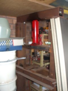
I was doing some work in the garage some 20 odd years ago and realised that I needed to be able to apply pressure to install and remove bearings as well as press out oil and/or perhaps grape juice, bend metal and a host of other things that need the application of pressure over a small area. I decided I needed a press and that the cheapest way was to build one, so I took my welder, bench drill and other tools in hand, not to mention a modicum of steel I had put away and proceeded to construct one. Before getting stuck into things it is worth noting a couple of points –
1. This is the way I did it, using available materials. So if you are intent on making a press too, look at the principles involved before ordering 3000tonnes of mild steel, and
2. The press is very over designed when used with a 10 tonne jack, but the steel was what I had on hand at the time.
The press is made up of the following parts –
A. Two uprights made from 150mm x 75mm mild steel channel
B. Two spacers used at the bottom to separate the uprights made from 64mm x 25mm angle iron
C. Two “feet” to stop the press from falling over during use, made from 75mm x 75mm angle iron
D. The table on which the work to be pressed sits, was made from two lengths of 50mm x 100mm mild steel channel joined by two lengths of 25mm x 25mm angle iron.
E. The pins on which the table sits which are made from a length of 16mm diameter steel bar
F. The moving member which does the work (ie it moves down and applies pressure when the press is in use) which is made from 50mm x 100mm channel with 25mm x 25mm welded on top to stop it flopping about, and a lump of 50mm steel bar welded onto the bottom face that applies the pressure.
G. The top brace against which the jack pushes, made from 100mm x 100mm steel RHS
H. The bit what applies the pressure, which will be discussed in more detail later.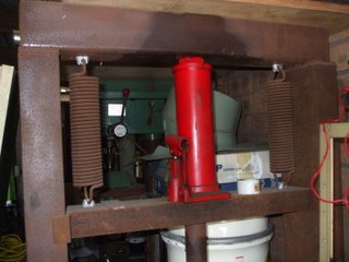
All the cuts were made with an oxyacetylene set and the rough ends cleaned up with a 100mm angle grinder.
I made the press as follows –
The uprights (which seem to weigh a tonne!) were marked out drilled with a morse taper 13/16” drill to produce holes 150mm apart. These are to take the pins that support the table. I drilled one hole in each 75mm face of the upright so that the table sits flat on the pins when inserted in these holes once the press is assembled. I then marked out 10 holes down the face of the uprights to allow the table to be adjusted in height at 150mm centres using a centre punch and then drilled ¼” pilot holes with a hand drill. Next I levered the heavy uprights on their side onto the table of my bench drill and drilled in the 13/16” holes to take the pins (I’d hate to try that with a hand drill!). The 13/16” holes meant that there was an easy fit for the pins, but also, it was the only size drill I had that came close to being the right size, so you have to use what you got!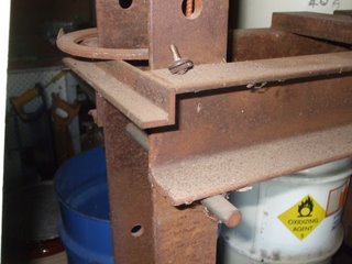
The ten holes in each face now drilled (40 in all) I could stand the uprights back up and bolt on the top brace to the top of the uprights using a plate I had previously welded across the open part of the top of the channel. I used 4 x 12mm bolts on each side – it wasn’t going anywhere! One the top brace was on I wrestled to keep the uprights, upright and at 90° to the floor while I welded the spacers in place at the base of the uprights. The 75mm x 75mm angle iron “feet” were then welded on the bottom to keep the press superstructure straight and upright.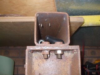
The next step was to insert the pins into a set of holes and place the 50mm x 100mm channel on them, on its side to form the working part of the table. I welded 25mm x 25mm angle iron onto the ends of the channel, outside the uprights so that the table formed a box around the uprights that was hopefully level and stable but still moveable.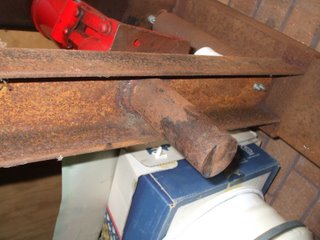
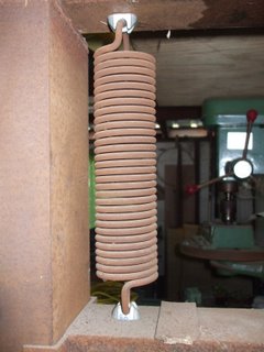
The moveable member then needs to have the 50mm diameter steel bar (the bit that does the pushing) welded to the moveable member. I only have a stick (arc) welder so I got a mate who is a welder by trade to weld it on with MIG because it is a bit difficult to get to inside the channel. That done I welded on some of the 25mm x 25mm angle iron on the end of the channel so that they curve around the uprights and keep the moveable member steady. Once fitted into the uprights I suspended it from the top brace using two large springs held onto the 100mm x 100mm RHS top brace and moveable member with cable clips.
The springs are a story in themselves, I spent quite a bit of time trying to find off the shelf springs that would be strong enough to support the moving member and the hydraulic jack without being so tight as to prevent the jacks’ correct operation. In the end I found a local spring manufacturer in the industrial estate that I was working at the time and explained what I wanted to do. The custom made me two springs that were perfect, for only $10 a piece, although that was 20 odd years ago and they might cost a bit more now.
Now comes the bit that does the work the hydraulic bit that applies the pressure and turns a large lump of metal into a functioning press. There are three types that could do the job –
1. A conventional hydraulic jack, similar to the bottle jack you would use to change a tyre on your car.
2. An upside down hydraulic jack
3. A hydraulic ram and pump like a Porta Power or similar
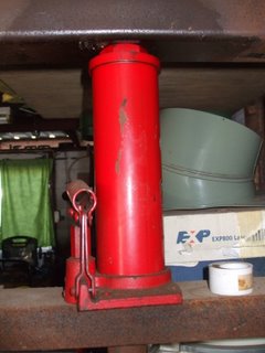
The conventional hydraulic jack is cheap, easily available and versatile. It can also be used to jack up vehicles in its spare time. The upside down jack is more expensive and virtually useless for anything else but, when mounted directly on the top brace, it would allow you to do without the moving member and springs by applying the downward force directly. The hydraulic pump and ram are used commercially in hydraulic presses, they also allow the moving member to be done away with and are very versatile, but even a second hand one can cost three time the price of a new jack of the same pressure.
Needless to say I chose option 1, but rather than just buy a jack I bought a hydraulic pipe bender at a approximately twice the cost of the jack. This gave me two tools I could use and a jack that can be used on its side (many hydraulic jacks can’t be) so I can build it into a home made log splitter, when I get the time. Mind you I have had the thing for over 20 years and the log splitter hasn’t materialised yet! But I do still have a very versatile hydraulic hand operated power source. Considering my likely uses and current costs I chose a power plant with 10 tonne capacity but it was personal choice.
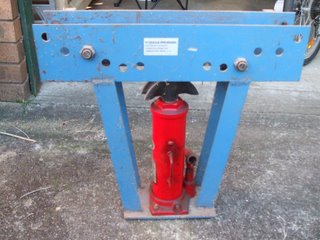
The press was completed just a few days before one of the bearings in my car alternator very noisily gave up the ghost. Instead of having to buy a new or reconditioned alternator I dismantled it, pressed out the old bearings and pressed in the new ones. At $12 for the pair it was a cheap repair job, giving me an almost new alternator, so the press had started to pay for itself already.
