


This article was first published in July 1982 as “Survival Push Bike Pt2” in the magazine Australasian Survivor and was written as part of a three part series by the then editor, Mr Bill Tarplee. Bill is a wizard with things mechanical and his advice and insights are still relevant today for those who wish to live more sustainably by using their bike.
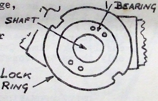
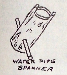
With the cranks off you can now get access to the bearing. You will find that only one side is removable. Also, the bearing differs slightly in that it doesn’t use cones, instead an adjustable ball race is locked in position with a locking ring (it is almost the cone system in reverse). The locking ring has slots milled in the edge for tightening and removal. There is a special half moon spanner made for just this nut. Either buy the correct spanner or make up a tool as shown. Lazy people don’t bother with the correct tools and use drifts; this in turn damages the slots. Do the right thing and get the proper tool now, while such tools are readily available at reasonable prices. Making your own spanner isn’t a bad idea as it will give you practice and saves a bit of money as well. Either way, having the correct tools will stand you in good stead and could give you a ready source of income in the coming bad times. No matter how bad things get, many people will still be ready to pay good money for a job well done and you could be setting yourself up for a future business when earning money won’t be so easy.
The greasing and adjustment process is similar to that already discussed. The one thing to watch is the refitting of the cranks. The left hand pedal spindle is threaded anticlockwise. This means that the normal pedalling action will tend to tighten the spindles. This it is important that the appropriate crank be fitted to each side. It is often a good idea to mark the cranks before removing them, but you will often find that the manufacturer has stamped L an R on the inner face of the spindle. If this is the case you won’t need to mark them.
I mentioned in Part 1 about replacing the cotter pins. These are a cylindrical pin with a taper milled along one side. Often they are made slightly oversize to allow for wear. It should not be necessary to drive them home, as they should be a snug fit only. Firstly try them in the crank hole while it is off the bike. If the pin fits the hole you won’t have to do any work on the circumference. (If it won’t go right through, try it from the other side). If it won’t go either way you will have to relieve the outside of the pin slightly. I do this with a fine file, removing metal equally over the cylindrical surface only, until I get the pin to project some four threads out the other side. Once this is done you can then fit the crank to the shaft. (smear a bit of grease over the shaft and around the pin). Try pushing the pin in, while slightly rocking the crank. Bear in mind that it is designed to fit from one side only, so it will go further through on one side than the other. Quite often it will be necessary to file a bit off the flat, but before you do so be sure that you have located the right side. Some lairs just use the back of an axe to persuade the pin to fit, but they will pay for that in the next life – do it properly! Also, if you have to file, keep the face at the same angle as it must bear across the entire surface.
Once you have a neat fit, give the pin a light tap with a hammer and do up the nut (using a washer of course). Also, make sure that the pin is still greased and that there is grease on the threads. Then it will come out easily next time. Don’t over tighten the nut either, as it is only there to stop the pin falling out again.
Drive Mechanics
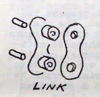
The part that receives a lot of abuse under most adverse conditions is the chain. Chains may vary slightly to the degree that sometimes a different type is fitted to the external (derailleur) gears. These chains have more sideways movement built in, so that the chain can ride freely over the sprockets when changing gears. The important question is whether the chain will move in a lengthwise direction under tension – i.e. “stretch”. This gives greater distance between the rollers and causes increased wear upon the backs of the sprocket teeth. If there is much wear you can’t do much but throw the chain away. Such wear is easier prevented by simply cleaning the chain frequently , and applying a light oil to the links. As an example, I clean and oil my chain every weekend – about every 150 km. It only takes a few minutes, and prevention has always been better than cure.
I simply get a small tin of kero and an old paint brush and paint all the oily or greasy surfaces with kero, as previously described (including all the derailleur gears). Once the oil is runny with kero, I hose it off with the garden hose and leave the bike in the sun for ten minutes or so. As soon as the chain, sprocket, gears etc. are dry I apply a light coating of thin oil. The bottles of Singer sewing machine oil are ideal for this purpose. As an alternative, some people like to spray on WD 40, RP 7 or a silicone spray lubricant. I will agree that the silicone sprays do not collect dirt as readily, but they still pick it up, so you will have to clean the chain almost as frequently. The oil is a lot cheaper and will be easier to obtain in hard times so I recommend you get into the habit of using it now, and stock away a supply while it is still only 50 cents (1980s prices) a bottle.
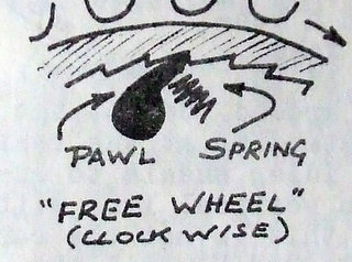
I have elected to include the freewheeling device under the “Drive Mechanics” section simply because it is located inside the rear wheel sprockets. Basically, the freewheeling mechanism is a set of (usually) two pawls inside the rear wheel cluster. It gives very little trouble and lasts for a very long time. However it does need maintenance from time to time. It can only be worked on with the rear wheel removed. If you stud the gear cluster you will notice that there is an inner ring screwed into the gear periphery. There are two holes in the inner ring, and I guess there is a special spanner to suit, though I haven’t found one as yet. The ring is hardened so I use a 2 inch wire nail as the punch (nails are very soft steel). With the nail in one hole then laid over to an angle of 45 degrees, one blow from a hammer is usually sufficient to loosen the ring. The important thing is to determine which way the thread ruins before you start. Normally it is a right hand thread (clockwise tightening) so you point the nail anticlockwise. If in doubt, get a fine nail, pin, probe or wire and run it in the thread. You can readily determine which way it tightens and loosens. I have found that an old dental pick is most useful for this purpose.
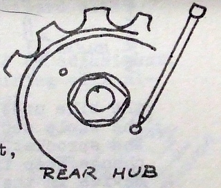
Once you have removed the retaining ring, you will find that there are two sets of ball bearings inside the gear cluster. The balls are small and numerous and it is important that you don’t lose any. Use a magnet to collect them or work over a bag. Clean up all the parts, taking care to note how the parts are fitted before you remove them. (I know a bloke that bought an old school slate for just this purpose; he draws a “mud map” as he goes and if necessary will also number the parts with a felt pen just to be sure.) Then clean up with kero and grease before reassembly. It is best to do the freewheel mechanism at the same time as the rear wheel bearings, as you can clean everything properly at the same time.
To be frank, I haven’t had any experience with internal hub gears. I have seen a few diagrams over the years and I would simply follow the steps I have already laid out, putting the pieces in order as I removed them, but also taking the time to study how it worked as I went. There are no prizes for having any pieces left over! Clean everything carefully and reassemble with light grease. Read the next section in conjunction with this, as the two are closely related.
Derailleur gears are simple in action and easy to adjust (which is contrary to some opinion). Simply, the system divides into two parts – the front drive sprockets and the rear driven sprockets, with a chain tension device to take up the tension on the chain.
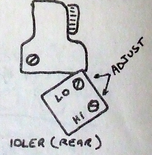
Moving the rear hub selector lever causes the trailing idler arm to move laterally. It must move from the inner gear to the outer, without any extra movement to either side. The limits of this movement set by tow small screws on the idler arm. I’d suggest you don’t tamper with the gears unless the chain is jumping off either sprocket. If the chain shows a tendency to jump off while pedalling, then take the following measures – Raise the rear of the bike so the wheel is clear of the ground. Select the highest gear by the lever, then while standing at the rear of the bike, sight the idler wheels to make sure that they are in a vertical line with the chain sprocket. If this is not the case, slowly turn the screw marked “H” until the idler pulleys and the sprocket line up vertically. Then crank the pedal while changing gears to the lowest gear. If the line-up is not perfect, adjust the “L” screw until it is. (Usually there is very little screw adjustment required – maybe ½ to 2 turns maximum.) Usually that is all that is required.
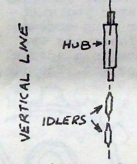
Test the bike under load to be sure that the adjustment is correct. The whole secret lies in getting the idler to line up with the sprocket, since it is the idler that causes the gears to change. Keep in mind also that while there is a free wheel device in the hub, you should not pedal backwards. Even with perfectly adjusted gears such action will occasionally cause the chain to jump off. I suspect that this is simply because of the lateral movement built in to the chain.
The front sprocket change is adjusted in a similar way, only there is more latitude for the selector movement, since it is required to cover a much shorter lateral difference. Usually you will find that it does not lake full movement of the lever to shift the chain. Thus is high drive gear is selected at the top of the lever travel, low gear will be at about half the lever travel, not at the bottom of the lever arc. You could adjust the whole system so that Low was at the very bottom of the lever arc, though this is not usually done. Then you would find that high would be at about half level travel.
With both sections of the derailleur system, check to see there is not excessive wear. Some idler wheels are a type of plastic, and wear fairly quickly. The front chain guide also wears on the sides and may require replacing. Further, you should remember that jumping gears may be a sign of excessive chain wear, not poor adjustment. Thus if it jumps gears and the idler wheels are in a vertical line, suspect the chain or sprockets, or both.
One other point – jumping gears can be a sign of misuse. No bike gears are designed for changing under load. You should always change gears before load is incurred. This if you are about to climb a steep pitch, or start off from the lights or whatever, go down to the gear you will need while you are still rolling. This way the chain is aligned and squarely seated before the load is introduced. It is much kinder to the machinery and prevents excessive wear. If it is necessary to change gears on a hill, just reduce the load on the pedals while the chain is shifting. You can do this quickly with practice, and you won’t lose much momentum.
One last point about gears is the selector cable. In both internal and external gears the cable should not have any slack. This is particularly true of the internal gears. The cable must be in slight tension, even in first gear (I once had to fix a three speed hub gear that only had two operable gears. I was all set to rip the whole thing apart, but I had a flash of inspiration and studied the linkage operation while slowly cranking by hand. I found that the selector movement was travelling half way just to take up the slack in the cable. One minute’s work and I was a “wizard” with bikes.”)
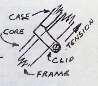
The cables rarely have any inbuilt method of adjustment. Usually you have to shift the rear cable retaining clip along the frame. Moving the clip toward the front of the bike tensions the cable and moving the clip to the rear slackens the cable. Normally such movement would be sufficient . Should it happen that the cable has become unduly stretched, I shall discuss shortening cables later on. At the same time i would point out that such treatment is rarely required and I’d look to all other caused before chopping up the cable.
Brakes
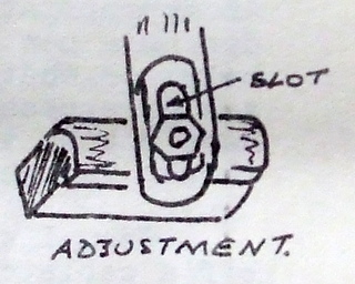
There is very little that I can write about brakes that is not obvious. The brake shoes are replaceable and should be thrown away once the wear is approaching the metal backing plate. When replacing the shoes, or even adjusting them, make sure that you are getting maximum surface contact on the rim. Bike brakes are never totally effective and it is important that you obtain maximum rim contact. Most brakes have and slot adjustment so that the shoes can be raised or lowered to match the rim. Also the brakes are badly affected by moisture which tends to lubricate the rim. I have been riding in fog and found that the small amount of moisture is sufficient to reduce braking effectiveness to near nil for the first twenty feet of action. If the shoes don’t have full rim contact, this distance will be greatly increased.
Should circumstances arise that you could not obtain brake shoes, I would look to cutting a pair from an old car tyre. I feel confident that they would work satisfactorily. The regular shoes are glued onto the backing plates. I would prise the old shoes out with an old screw driver and either glue or wire the new shoes in their place.
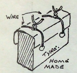
If it becomes necessary to make your own brake shoes – keep one tip in mind. You will need a very sharp knife to cut a tyre. On its own this will probably not be sufficient; you should mix up a bit of soap and water to make a lubricant. Thoroughly wet the knife and rubber and you will be able to cut it without any trouble at all. I should also point out that you should not try to cut the tread of steel belted radial tyre, as it would have a number of layers of hardened steel wire impregnated into the rubber. Look for a conventional cross ply or textile radial, and it will save both your knife and your temper. (These types of tyre have become rare as hens teeth, try used conveyor belting as discussed in the article on replacing the sole on a pair of sandals, located in the “craft” section.)
Lastly, when adjusting brakes, don’t make the adjustment too fine. The current “side pull” brakes don’t centre very well. Thus you will find that even when the brakes are fully slackened on shoe frequently skims the rim. While this contact is not excessive, it is a constant drag on the bike and it becomes very wearing after a few miles. It is better to have a bit more free travel and no possible interference on the rim.
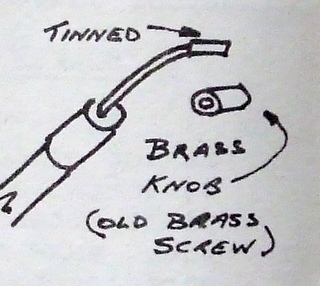
Brake cables require very little maintenance. A couple of drops of light oil down the throat of the casing so that it will run down the core and keep it lubricated, and a bit of grease on any exposed core is pretty well all that you can do. If a cable breaks in hard times, don’t throw it away. Back when I wore short pants you could still buy brake cable by the length – 3 feet of casing and 3 feet six inches of core, for example. Buy two special brass knobs to suit, and home you went. Just “tin” the ends of the core with solder, slip on a brass knob and sweat solder the joint. Do the same at the other end and you were set. Since cables mostly break at the knob, you would only be losing 15 to 25 mm of cable if you were to cut and appropriate length from the casing and solder on a new knob made from a brass screw or bold or what-have-you. Most modern cables are of excessive length anyway, so you usually have plenty to play with. Those not “in-the-know” would have thrown the whole thing away.
When I was a kid, one bloke I knew who broke the end off a cable cut about 200mm off the end of the casing and then tied the core around the top bar near the handle bars. To stop he just pulled up the casing and the brakes worked. Very primitive, but who knows when.......
Lastly – in a pinch you could make brake and gear cables utilising other materials. The plastic coated coiled wire used for kitchen curtains would make a casing and fishing trace would make a core, Alternatively you could just shorten gear cables, as these are always much longer than brakes.